Today, I focused on enhancing the realism and practicality of my RF power amplifier (PA) simulation by replacing all ideal passive components with actual Murata surface-mount device (SMD) parts. The goal was to move one step closer to a production-ready design by simulating how the circuit would behave with real-world inductor and capacitor values that include parasitic effects.
To begin, I substituted every ideal capacitor and inductor in the circuit with Murata parts, specifically from the GRM and LQW18 series. These include high-Q ceramic capacitors (GRM1555C1H620JA01, GRM1555C1H910JA01) and wire-wound inductors (LQW18AN series), selected to closely match the ideal values used in the earlier design. These real components introduce parasitics and tolerances that affect the circuit’s frequency response, matching, and efficiency factors which I carefully accounted for through iterative tuning.
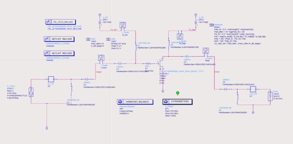
Fig .1: Schematic of Power Amplifier With Murata Components
To support this selection process, I made use of Murata’s SimSurfing tool, which provides detailed characteristics for each component, including Q-factor, RDC, self-resonant frequency, and impedance profiles over frequency. This tool was extremely helpful in understanding the electrical behavior of each part beyond just nominal values. By studying these parameters in detail, I was able to select components that offered the best trade-off between low loss, high selectivity, and size constraints all of which contributed to refining my design for real-world conditions.
To further enhance the harmonic rejection and ensure clean signal transmission, I designed and implemented low-pass filters (LPFs) at both the input and output of the amplifier chain using real Murata components. The LPFs were carefully constructed using Murata’s LQW18AN series inductors and GRM1885C series capacitors, chosen to provide sharp roll-off while maintaining low insertion loss in the desired 161–162 MHz frequency band. The input LPF consists of components like LQW18AN82NG80, LQW18AN20G80, and GRM1885C1H150JA01, while the output LPF includes parts such as LQW18AN43NG80, LQW18ANR18J80, and GRM1885C1H120JA01. After tuning the values, I achieved an insertion loss of less than 0.9 dB, which confirms the filters are well-optimized and meet the required performance standards without significantly degrading signal strength.
Following these updates, I performed harmonic balance and S-parameter simulations to analyze the amplifier’s performance. The results were very promising. At 161 MHz, the amplifier delivered 4.638 W (36.66 dBm) of power to the load, with only 36 mW of input drive. The measured power-added efficiency (PAE) reached an impressive 56.1%, and the drain efficiency (Deff) was approximately 56.5%. Moreover, the overall gain was measured to be around 20.66 dB, indicating that the PA is operating well within the desired performance range. From the S-parameter results, I observed a forward transmission (S21) of 26.67 dB at 161 MHz, with excellent input and output matching: S11 and S22 were -17.62 dB and -21.02 dB respectively. This confirms that both the filters and matching network are working effectively, even with the added complexity of real component parasitics.
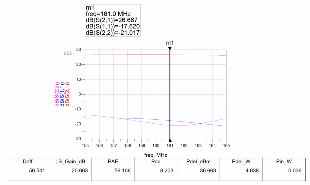
Fig .1: Simulation of Power Amplifier With Murata Components
Here are the Results:
| Parameters | Value |
| Frequency | 161 MHz |
| Pdel (Delivered Power) | 4.638 W |
| Pdel_dBm | 36.663 dBm |
| Pin_W (Input Power) | 0.036 W |
| LS_Gain | 20.663 |
| PAE (Power-Added Efficiency) | 56.106 % |
| Deff (Drain Efficiency) | 56.541 % |
| Pdc | 8.203 W |
| S21 (Forward gain) | 26.667 dB |
| S11 (Input return loss) | -17.620 dB |
| S22 (Output return loss) | -21.017 dB |
Moving forward, I plan to further optimize the design by refining the selection of Murata components to more closely match the ideal values used in initial simulations. This involves carefully reviewing the available Murata capacitor and inductor series to identify components with tighter tolerances, higher Q-factors, and minimal parasitic effects at the operating frequency of 161 MHz. By doing so, I aim to reduce the insertion loss of both input and output low-pass filters to below 1 dB ideally approaching 0.5 dB without compromising harmonic suppression or impedance matching. Additionally, I will perform sensitivity analyses and parametric sweeps within the simulator to assess the impact of each component on overall system performance. These improvements will help push the design closer to hardware-ready quality, ensuring that the amplifier maintains high efficiency, strong output power, and excellent RF characteristics in a real-world implementation.
In conclusion, today’s work marks a significant milestone in transitioning from idealized simulation to a more realistic and manufacturable design. By integrating real Murata components, studying their behavior using SimSurfing, and refining the LPFs, I ensured that the amplifier maintains high efficiency and excellent RF characteristics. These improvements not only validate the robustness of the design but also pave the way for PCB prototyping and eventual hardware implementation.
Leave a Reply