In one of my recent RF design tasks, I worked on building a matching network to connect the RF output of the Silicon Labs Si4463 transceiver to the external power amplifier (PA) having 50-ohm input impedance. The Si4463 has a built-in high-efficiency switching PA that can deliver up to +20 dBm, but to use it effectively with an external PA, proper impedance matching is critical. My goal was to make this match work cleanly at 161 MHz, using Keysight ADS for simulation and a Split TX/RX configuration.
To approach this correctly, I dove deep into Application Note AN648 from Silicon Labs. This document is a goldmine when working with their switching PAs. It explains that unlike traditional linear amplifiers (like Class A or B), the Si4463’s PA operates in switching mode, which means standard matching techniques won’t apply. AN648 outlines two key matching strategies depending on the operating frequency: Class-E matching, which works well above 260 MHz, and Square Wave with harmonic termination, which is better suited for lower frequencies like 169 MHz. Since 161 MHz falls in the lower range, Square Wave matching was the obvious choice.
Class-E matching is very efficient and works great at higher frequencies (like 868 or 915 MHz). It uses a carefully tuned resonant network to shape the voltage and current waveforms in a way that reduces power loss. But below 260 MHz, Class-E starts to break down—waveforms get distorted, harmonic suppression becomes tricky, and overall performance drops. That’s why for 161 MHz, I followed the Square Wave matching method described in AN648.
Square Wave matching takes a different approach. It focuses on creating a low impedance at the fundamental frequency (161 MHz in this case), while using a trap network to terminate harmonics. I followed the recommended component values from AN648’s 169 MHz example: a 390 nH choke inductor, 470 pF series cap (C0), and a trap made up of an 82 nH inductor and 11 pF capacitor. This is followed by a series of LC stages using inductors and capacitors to further suppress harmonics.
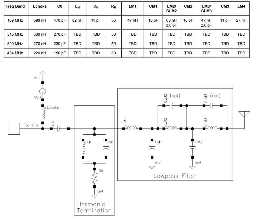
Fig 1: Square Wave Matching Topology for Split TX/RX Board Configuration with Frequency vs Component Values Table
At this point, I had to ask myself: Can I use these 169 MHz values directly for my 161 MHz circuit, or do I need to recalculate everything? The answer is a bit nuanced. Since 169 MHz is close to 161 MHz just under a 5% difference it’s reasonable to start with those values. But in RF design, even small frequency shifts can affect tuning, resonance, and harmonic behavior. So while the 169 MHz values are a good baseline, I’ll likely need to tweak component values like C0, LH, and CH to get the network perfectly aligned for 161 MHz. That tuning will happen either through refined simulation or better yet, real-world testing.
One major roadblock I ran into was that the Si4463 datasheet doesn’t specify its RF output impedance. This is a critical piece of information without it, I couldn’t perform a true conjugate match to the 50-ohm input of my PA. That meant I couldn’t run accurate simulations of return loss (S11), power delivery, or harmonic behavior in ADS. Unfortunately, this is common with commercial RFICs. Internal PA details are often treated as proprietary, so the only option is to rely on reference designs like those in AN648 and fine-tune later using test equipment. Despite that limitation, I moved forward by implementing the recommended 169 MHz values in my schematic as a first step. While these values are optimized for matching to a 50-ohm antenna or RF connector, they’re still a reasonable approximation for matching into a 50-ohm PA input.
From this study, I got to know that while the component values provided in AN648 for 169 MHz are not tailored exactly for 161 MHz, they are close enough to be used as an effective starting point for my design. The frequency difference is small, but in RF design, even a few megahertz can influence impedance matching, resonance, and harmonic suppression. Therefore, although I can begin with the 169 MHz values, I will need to fine-tune the matching network specifically for 161 MHz to ensure optimal performance. This will involve measuring the actual output impedance of the Si4463 on the physical board using a vector network analyzer and adjusting key components like C0, LH, CH, and the filter stages. Overall, this study helped me understand the importance of starting with validated reference designs while also recognizing the need for practical tuning based on real-world measurements to achieve accurate matching in a sub-GHz RF system.
Leave a Reply